
905nm
905nm Multi Junction VCSEL Bare Die Series
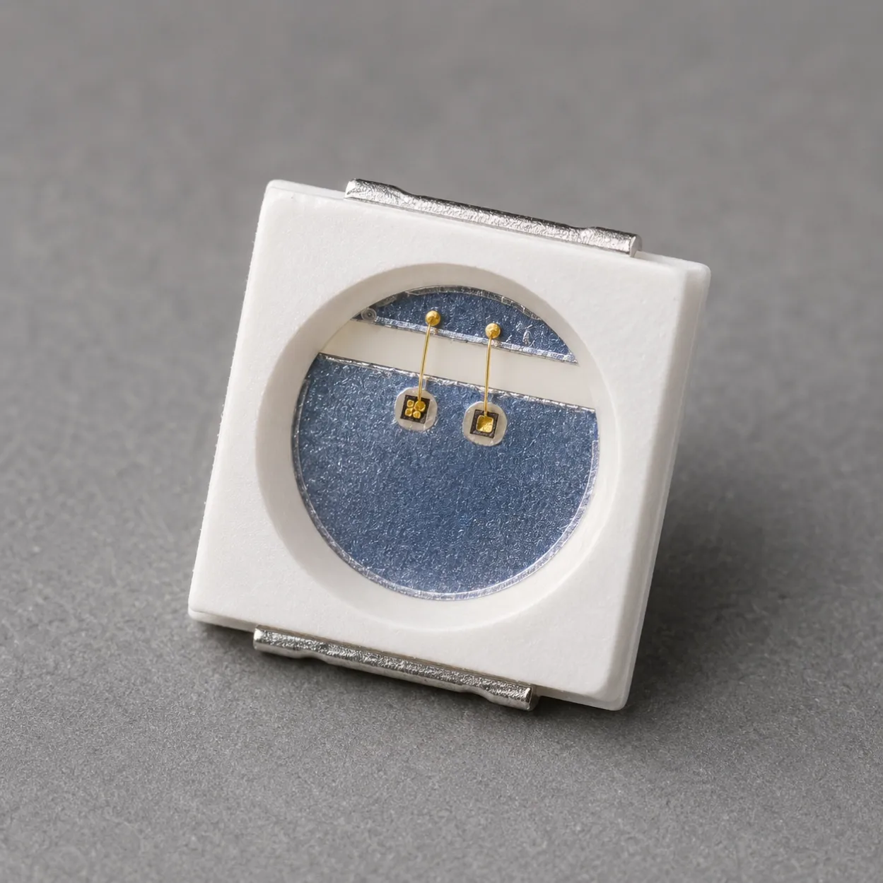
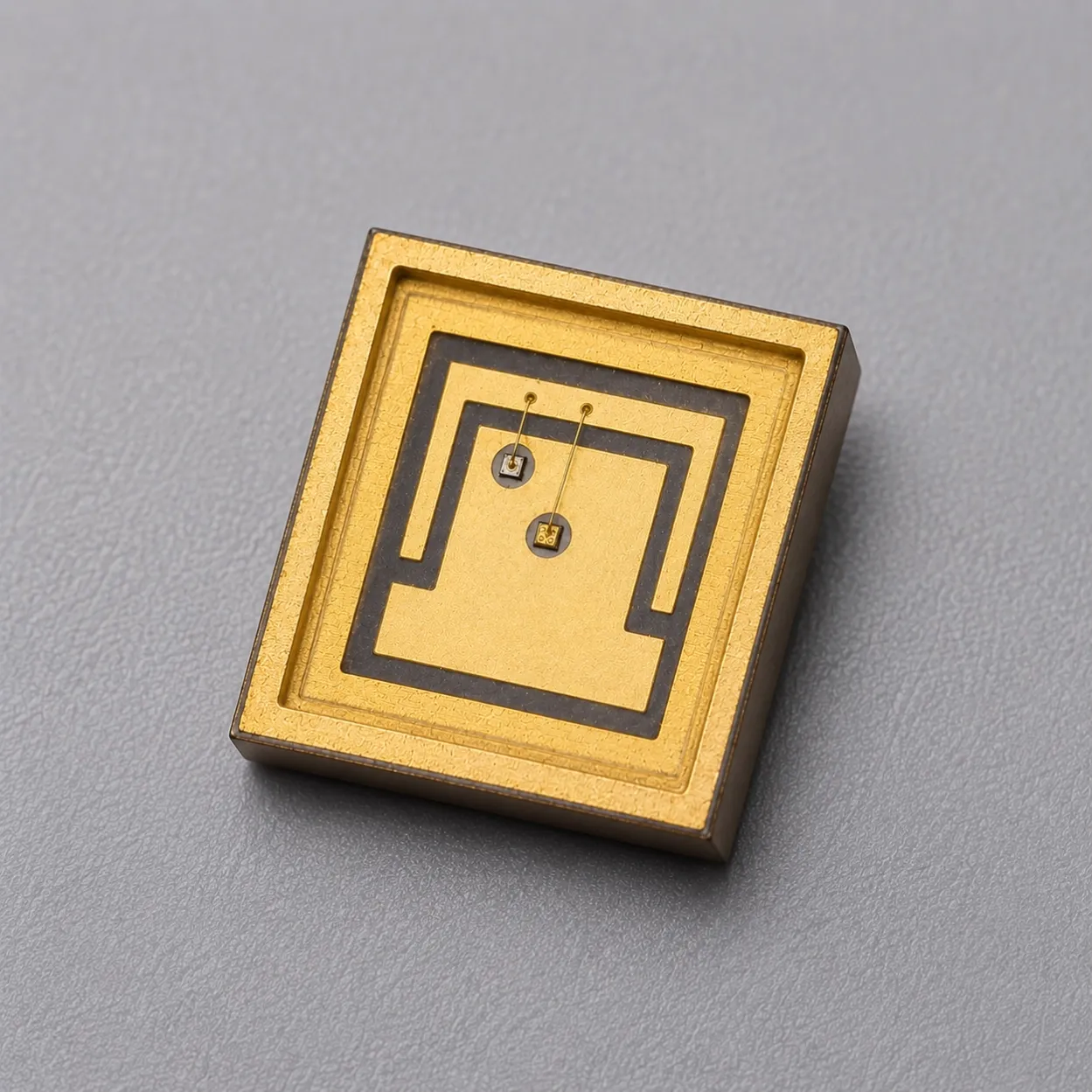
905nm multi-junction VCSEL bare die series with 1W, 4W, 7W and 70W pulsed options for rangefinding, distance measurement and OEM custom packaging.
Specifications
- Product Type
- Multi-Junction VCSEL Bare Die
- Wavelength
- 905nm typ.; 895–915nm
- Optical Output Power
- 800mW min. to 70W typ., model-dependent
- Emitter Configuration
- 1 / 1 / 7 / 52 emitters
- Operating Mode
- Pulse, 5ns pulse width, 0.1% duty cycle
- Die Size
- 180 × 180μm to 370 × 450μm
- Recommended Assembly
- Die Attach / Wire Bonding / Ceramic Submount / Custom Packaging
1. 905nm Multi-Junction VCSEL Bare Die Supply for Pulsed Source Packaging and Module Integration
The 905nm Multi-Junction VCSEL Bare Die Series includes four nanosecond-pulsed near-infrared source options for rangefinding, distance measurement and industrial sensing, semiconductor packaging and custom optical-module integration.
The available models include 1W, 4W, 7W and 70W pulsed-output classes. All four products provide a typical peak wavelength of 905nm within a specified wavelength range of 895–915nm.
The optical-output values are characterized at 25°C using a 5ns pulse width and 0.1% duty cycle. These ratings apply to controlled nanosecond-pulse operation and must not be interpreted as continuous-wave or long-pulse optical-output ratings.
The series combines two single-emitter devices and two multi-emitter VCSEL arrays:
- 1W single-emitter die with a 20 ±1μm emitting aperture
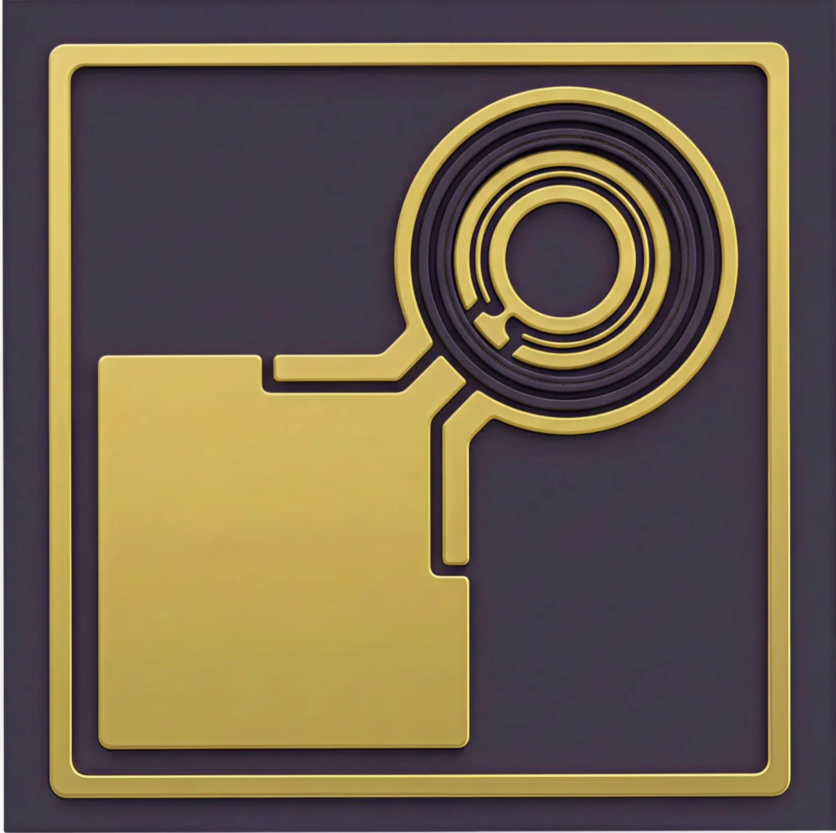
- 4W single-emitter die with a 50 ±1μm emitting aperture
- 7W die with a seven-emitter array
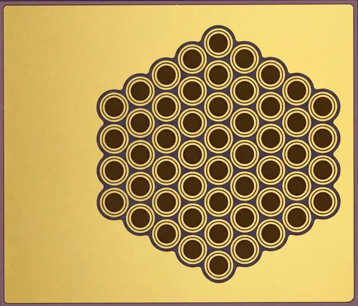
- 70W die with a 52-emitter array
The different optical-output levels, emitter structures, drive-current requirements and die dimensions allow engineering teams to select a suitable model according to transmitter architecture, package space, electrical parasitics, optical field, working distance and receiver requirements.
This series is intended for:
- Rangefinding and distance-sensing transmitter developers
- Laser-rangefinding and distance-sensing teams
- OSAT semiconductor assembly and test providers
- VCSEL and laser-diode packaging companies
- Nanosecond pulse-driver development teams
- Ceramic-submount and COB integrators
- Lens, diffuser and collimation companies
- Industrial sensing and object-detection developers
- Engineering laboratories and research institutions
- Technical sourcing and second-source development teams
Development directions include Pulsed rangefinding-source evaluation, industrial distance measurement, object and presence detection, nanosecond pulse-driver evaluation, custom ceramic packaging, low-inductance chip-on-board integration and application-specific optical modules.
The products are supplied as unpackaged semiconductor bare dies. Conductive die attachment, wire bonding, package protection, low-inductance electrical design and optical integration are required before use in a completed transmitter or optical module.
2. 1W, 4W, 7W and 70W VCSEL Bare Die Model Selection
The 905nm Multi-Junction VCSEL Bare Die Series provides four optical-output and emitter-layout configurations for nanosecond pulsed-source development.
All four models in the following table are characterized at 25°C using a 5ns pulse width and 0.1% duty cycle. Model selection should consider peak optical output, drive current, emitter count, emitting-aperture size, die dimensions, pulse-driver capability, package inductance, bond-wire configuration and optical-system requirements.
Product | Optical Output | Drive Current | Beam Divergence | Emitters | Die Size |
|---|---|---|---|---|---|
800mW min. 1W typ. | 200mA | 18° typ. 1/e² | 1 | 180 × 180μm | |
4W min. 4.5W typ. | 1A | 18° typ. 1/e² | 1 | 180 × 180μm | |
5.6W min. 7W typ. | 1.4A | 18° typ. 1/e² | 7 | 278 × 210μm | |
60W min. 70W typ. | 15A | 18° typ. 1/e² | 52 | 370 × 450μm |
The optical-output values apply only under the stated nanosecond-pulse conditions. The devices should not be compared by nominal wattage alone.
Selection should also consider single-emitter or multi-emitter structure, emitting-aperture size, peak pulse current, driver rise and fall time, package and PCB inductance, die dimensions, bond-wire configuration, required optical field, receiver sensitivity and working distance.
905nm 1W Multi-Junction VCSEL Bare Die
The 905nm 1W Multi-Junction VCSEL Bare Die provides 800mW minimum and 1W typical pulsed optical output at a specified drive current of 200mA.
It uses one emitter with a 20 ±1μm emitting aperture in a compact 180 × 180μm-class die. This model can support lower-current pulse-driver development, compact single-emitter optical sources, initial package evaluation and distance sensing or rangefinding prototypes.
905nm 4W Multi-Junction VCSEL Bare Die
The 905nm 4W Multi-Junction VCSEL Bare Die provides 4W minimum and 4.5W typical pulsed optical output at a specified drive current of 1A.
It uses one emitter with a larger 50 ±1μm emitting aperture while retaining a compact 180 × 180μm-class die footprint. The model can be evaluated when higher output is required from a single emitter and the pulse driver can provide a controlled 1A nanosecond pulse.
905nm 7W Multi-Junction VCSEL Bare Die
The 905nm 7W Multi-Junction VCSEL Bare Die provides 5.6W minimum and 7W typical pulsed optical output at a specified drive current of 1.4A.
It uses seven emitters with 20 ±1μm apertures in a 278 × 210μm-class die. The distributed emitting structure provides a compact multi-emitter option for custom ceramic packaging, transmitter development and optical-module integration.
905nm 70W Multi-Junction VCSEL Bare Die
The 905nm 70W Multi-Junction VCSEL Bare Die provides 60W minimum and 70W typical pulsed optical output at a specified drive current of 15A.
It uses a 52-emitter array in a 370 × 450μm-class die. This is the highest-output model in the current series and requires a package and driver designed for controlled high-current nanosecond pulses, current distribution and low electrical parasitics.
Related Articles
3. Packaging, Optical Module and Application Development
Bare Die Structure and Mechanical Integration
The four models use different emitting structures, die dimensions, thicknesses and electrode configurations. The selected package should be designed around the corresponding die rather than assuming that one electrical and mechanical structure can support every power level.
Mechanical Parameter | 1W Version | 4W Version | 7W Version | 70W Version |
|---|---|---|---|---|
Die Size | 180 ±10μm × 180 ±10μm | 180 ±10μm × 180 ±10μm | 278 ±10μm × 210 ±10μm | 370 ±10μm × 450 ±10μm |
Die Thickness | 150 ±10μm | 150 ±10μm | 150 ±10μm | 100 ±10μm |
Number of Emitters | 1 | 1 | 7 | 52 |
Emitting Aperture | 20 ±1μm | 50 ±1μm | 20 ±1μm | 20 ±1μm |
Anode Pad | Not specified | 90 ±3μm × 90 ±3μm | 175 ±3μm × 95 ±3μm | 330μm × 110μm |
Backside Cathode | Not specified | Full die area | Full die area | Full die area |
OSAT and Low-Inductance VCSEL Packaging
Possible integration formats include conductive die attachment, gold-wire bonding, ceramic-submount assembly, low-inductance chip-on-board integration and custom VCSEL transmitter packages.
Package development should consider:
- Die orientation and electrode structure
- Die-attach material
- Bond-wire length, quantity and current capacity
- Electrical-path symmetry
- Package and PCB inductance
- Ground-return structure
- Transient voltage overshoot
- Optical-axis alignment
- Mechanical protection
- Device temperature
For the 70W model, peak-current distribution, bond-wire current capacity, electrical parasitics and transient behavior require particular attention.
The dies are ESD-sensitive semiconductor components. Appropriate electrostatic-control procedures are required throughout storage, handling, die placement, wire bonding, package assembly and testing.
Lens, Diffuser and Optical-Module Integration
The bare-die format allows packaging companies and optical-module developers to select the submount material, electrical path, optical window, lens, diffuser, collimator and mechanical interface according to the transmitter design.
Possible development directions include:
- Ceramic VCSEL packages
- Low-inductance transmitter assemblies
- Chip-on-board optical sources
- Lens-integrated VCSEL packages
- Diffuser-integrated transmitters
- Collimated optical modules
- Customer-specific pulsed optical transmitters
- Application-specific rangefinding modules
The final optical field depends on emitter layout, die placement, package-window geometry, lens focal length, lens-to-die spacing, diffuser characteristics, mechanical tolerance and optical alignment.
For projects requiring completed surface-mount packages for direct PCB placement and reflow assembly, view the 905nm Multi-Junction VCSEL SMD Series.
Rangefinding and Distance-Sensing Development
The 905nm wavelength and nanosecond-pulse operation support near-infrared optical-source development for systems requiring short, synchronized transmitter pulses.
Application directions include:
- Pulsed rangefinding-source evaluation
- Pulsed distance-measurement systems
- Laser rangefinding
- Industrial distance measurement
- Object detection
- Presence and proximity sensing
- Optical trigger and timing systems
- Laboratory pulsed-source development
- Custom packaged VCSEL transmitters
- Optical-module integration
Product selection should consider peak optical output, pulse width, repetition rate, receiver sensitivity, detector timing, target reflectivity, optical transmission loss, transmitter field of view, receiver field of view, signal-processing architecture and operating environment.
The VCSEL bare die is one component of the complete transmitter system. Final detection distance, ranging accuracy and system performance depend on the driver, package, optics, receiver, timing electronics, signal processing, target conditions and environmental factors.
These component-level products do not independently establish the eye-safety classification, detection range or regulatory status of the customer's completed system.
For application-level sensing-source selection and optical-system planning, visit the Sensing & Machine Vision solution page.
For broader high-power NIR packaging and optical-module development, visit the High-Power NIR & Optical Modules solution page.
Distribution and Supply-Chain Support
The 905nm Multi-Junction VCSEL Bare Die Series is available to laser-component distributors, optical-module suppliers, technical sourcing companies and second-source development teams supporting customer packaging and transmitter projects.
Documentation, evaluation samples, selected model configurations and volume-supply requirements can be discussed according to the project stage.
4. Evaluation Kit and Documentation Support
The 905nm Multi-Junction VCSEL Bare Die Series is available as an Evaluation Kit with 10 pcs / KIT for pulse-driver development, die-attach evaluation, wire-bonding verification, package design and initial optical testing.
The Evaluation Kit includes:
- One selected 1W, 4W, 7W or 70W model per kit
- Corresponding product datasheet
- Corresponding die-dimension and assembly documentation
- International shipping quoted according to destination
Available evaluation options include:
- 905nm 1W Multi-Junction VCSEL Bare Die
- 905nm 4W Multi-Junction VCSEL Bare Die
- 905nm 7W Multi-Junction VCSEL Bare Die
- 905nm 70W Multi-Junction VCSEL Bare Die
Evaluation can support:
- Nanosecond pulse-driver testing
- Conductive die-attach trials
- Gold-wire bonding development
- Ceramic-submount evaluation
- Package-parasitic analysis
- Optical alignment
- Lens and diffuser selection
- Beam-profile evaluation
- Initial rangefinding and distance-sensing testing
- Initial rangefinding validation
The following requirements can be discussed according to the project:
- Peak optical-output selection
- Pulse width and repetition rate
- Pulse-current requirements
- Power-bin selection
- Die and bond-pad structure
- Low-inductance ceramic packaging
- Wire-bond configuration
- Lens and diffuser integration
- Beam-shaping requirements
- Custom transmitter modules
- Volume-supply planning
For component-level project evaluation, an Initial Product Report covering the Laser Diode Series and VCSEL Laser Diode Chip Series has been filed with the U.S. FDA CDRH. This filing supports technical documentation and product evaluation.
For applicable products, CE, EMC, EN 60825, LVD, RoHS, REACH and halogen-free certification and compliance documents are available. Documentation depends on the corresponding product model and does not represent certification of the customer's finished device.
5. Frequently Asked Questions
FAQ 1. What models are included in the 905nm Multi-Junction VCSEL Bare Die Series?
The series includes 1W, 4W, 7W and 70W pulsed-output classes. The 1W and 4W models use single emitters, the 7W model uses a seven-emitter array, and the 70W model uses a 52-emitter array.
All four devices are characterized at 25°C using a 5ns pulse width and 0.1% duty cycle. Selection should be based on required peak output, drive current, emitter structure, die dimensions, package design and optical-system requirements rather than nominal wattage alone.
FAQ 2. How should the 905nm VCSEL bare dies be packaged?
The products are supplied as unpackaged semiconductor dies and require conductive die attachment, wire bonding, package protection and appropriate ESD controls. The package should be designed around the selected die's electrode structure, dimensions and peak-current requirements.
Important factors include die-attach material, bond-wire arrangement, current capacity, package inductance, ground-return path, transient overshoot, optical-window design and external optics. The 70W model requires particular attention to current distribution, electrical parasitics and bond-wire capability.
FAQ 3. Should I select a 905nm VCSEL bare die or a completed SMD package?
Select a bare die when the project requires customer-designed semiconductor packaging, conductive die attachment, gold-wire bonding, ceramic-submount integration or a proprietary electrical and optical structure.
Select a completed SMD package when the project requires direct PCB placement, automated SMT assembly, reflow soldering and faster transmitter integration. The appropriate format depends on packaging capability, PCB architecture, electrical parasitics and optical design. Completed options are available in the 905nm Multi-Junction VCSEL SMD Series.