850nm
850nm 100mW VCSEL Bare Die
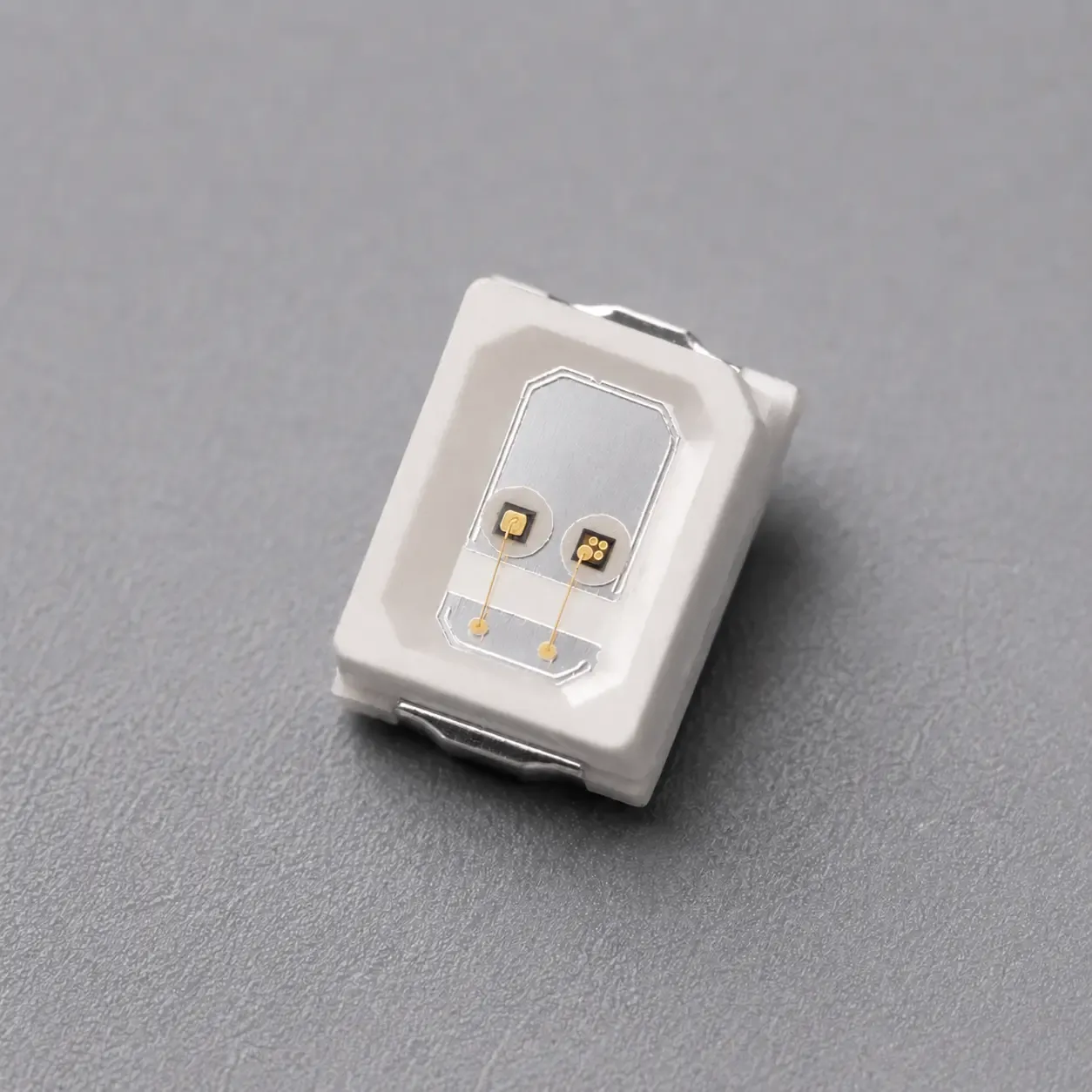
850nm 100mW VCSEL bare die with compact, square and rectangular die options for pulsed sensing, machine vision, wire bonding and OEM packaging projects.
Specifications
- Product Type
- Multi-mode VCSEL Bare Die
- Wavelength
- 850nm typ.; 840–860nm
- Optical Output Power
- 100–130mW, model-dependent
- Emitter Configuration
- 23 / 21 / 22 emitters
- Operating Mode
- QCW / Pulse
- Die Size
- 245 × 239μm / 300 × 300μm / 785 × 200μm
- Recommended Assembly
- Die Attach / Wire Bonding / Ceramic Submount / Custom Packaging
1. 850nm 100mW VCSEL Bare Die Options for Packaging and Optical Integration
The 850nm 100mW VCSEL Bare Die is available in three multi-emitter die formats for customers requiring different package dimensions, emitter layouts, pulse conditions and optical-source geometries.
The available configurations include:
- Compact 245 × 239μm die
- Square 300 × 300μm die
- Rectangular 785 × 200μm die
All three options operate in the 100mW power class and provide a typical peak wavelength of 850nm. However, they should not be treated as mechanically interchangeable versions.
The three products differ in die dimensions, die thickness, emitter count, anode-pad configuration, pulse width, duty cycle and output-power range.
This allows packaging companies and optical-module developers to select a suitable 100mW VCSEL die according to available package space, optical-source shape, electrical driving condition and wire-bonding architecture.
The products are supplied as unpackaged semiconductor bare dies and require die attachment, wire bonding, package protection, thermal-path design and optical integration before use in a finished product.
Development directions include:
- Near-infrared sensing
- Machine-vision illumination
- Industrial optical detection
- Proximity and presence sensing
- Compact multi-emitter optical sources
- Custom SMD and ceramic packaging
- TO-can package development
- Ceramic-submount integration
- Application-specific optical modules
- Engineering and research prototypes
2. Optical Configuration and Die Format Selection
The three available 100mW VCSEL bare-die configurations are compared below.
Option | Die Size | Die Thickness | Emitters | Optical Output | Test Condition | Beam Divergence |
|---|---|---|---|---|---|---|
Compact Die | 245 ±10μm × 239 ±10μm | 100 ±10μm | 23 | 100mW min. / 115mW typ. | IF = 140mA, 25°C, 1ms, 10% duty cycle | 20° typ., 1/e² |
Square Die | 300 ±10μm × 300 ±10μm | 130 ±10μm | 21 | 100mW min. / 120mW typ. | IF = 140mA, 25°C, 0.5ms, 1% duty cycle | 20° typ., 1/e² |
Rectangular Die | 785 ±10μm × 200 ±10μm | 130 ±10μm | 22 | 110mW min. / 120mW typ. / 130mW max. | IF = 140mA, 25°C, 0.1ms, 10% duty cycle | 20° typ., 1/e² |
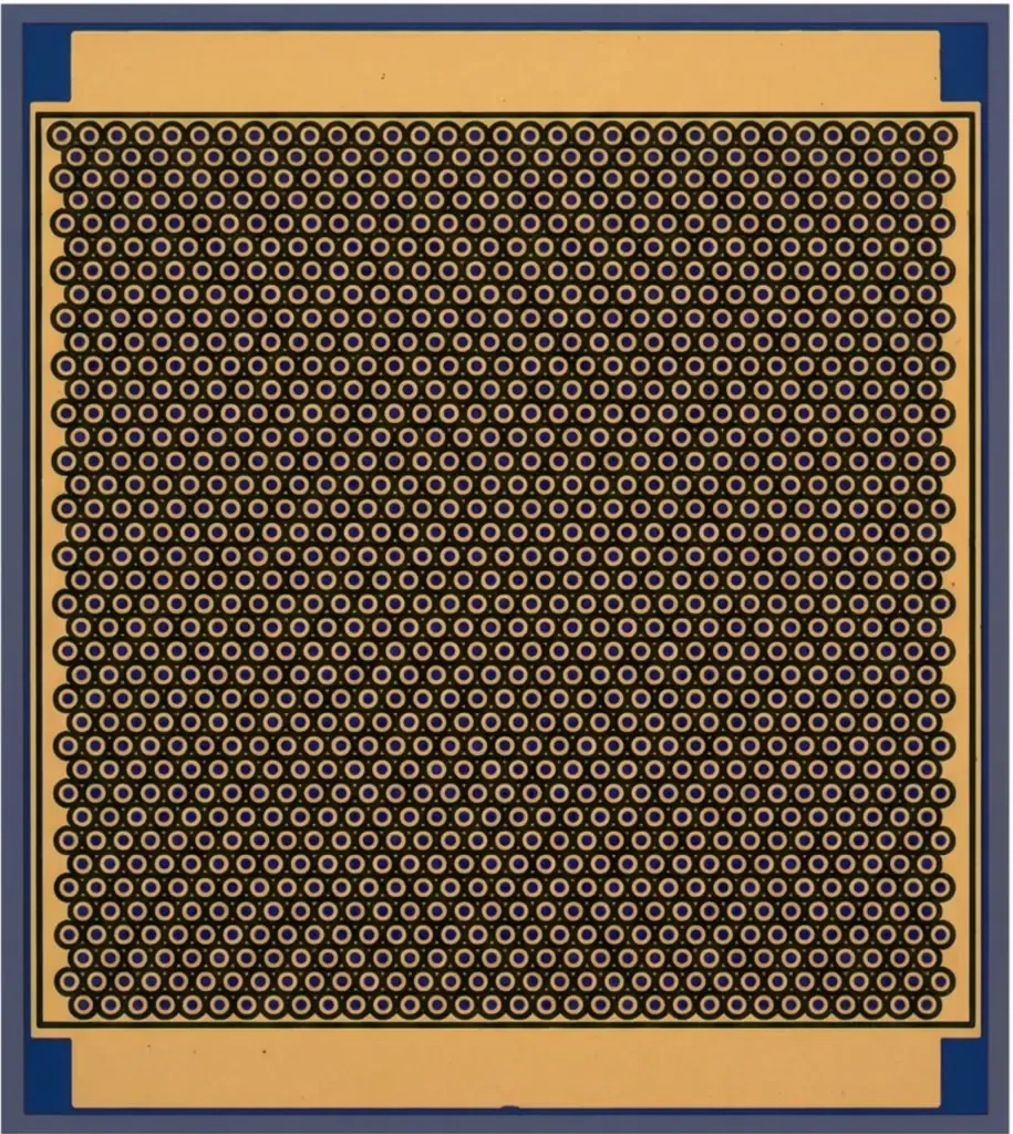
Compact 100mW VCSEL Die
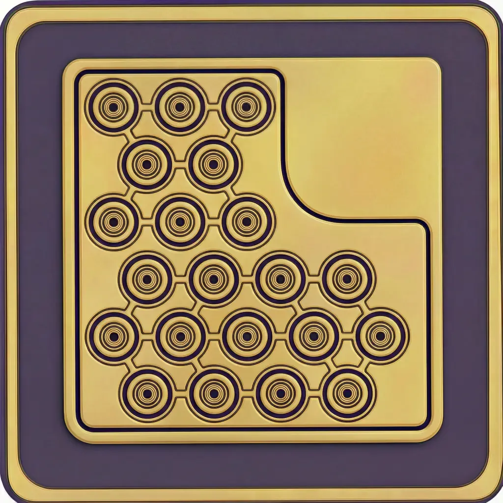
The compact version uses a 245 × 239μm-class footprint and a 23-emitter configuration.
It provides 100mW minimum and 115mW typical optical output at 140mA under a 1ms pulse width and 10% duty cycle.
This version is suitable for projects requiring a compact multi-emitter die and a relatively small package footprint.
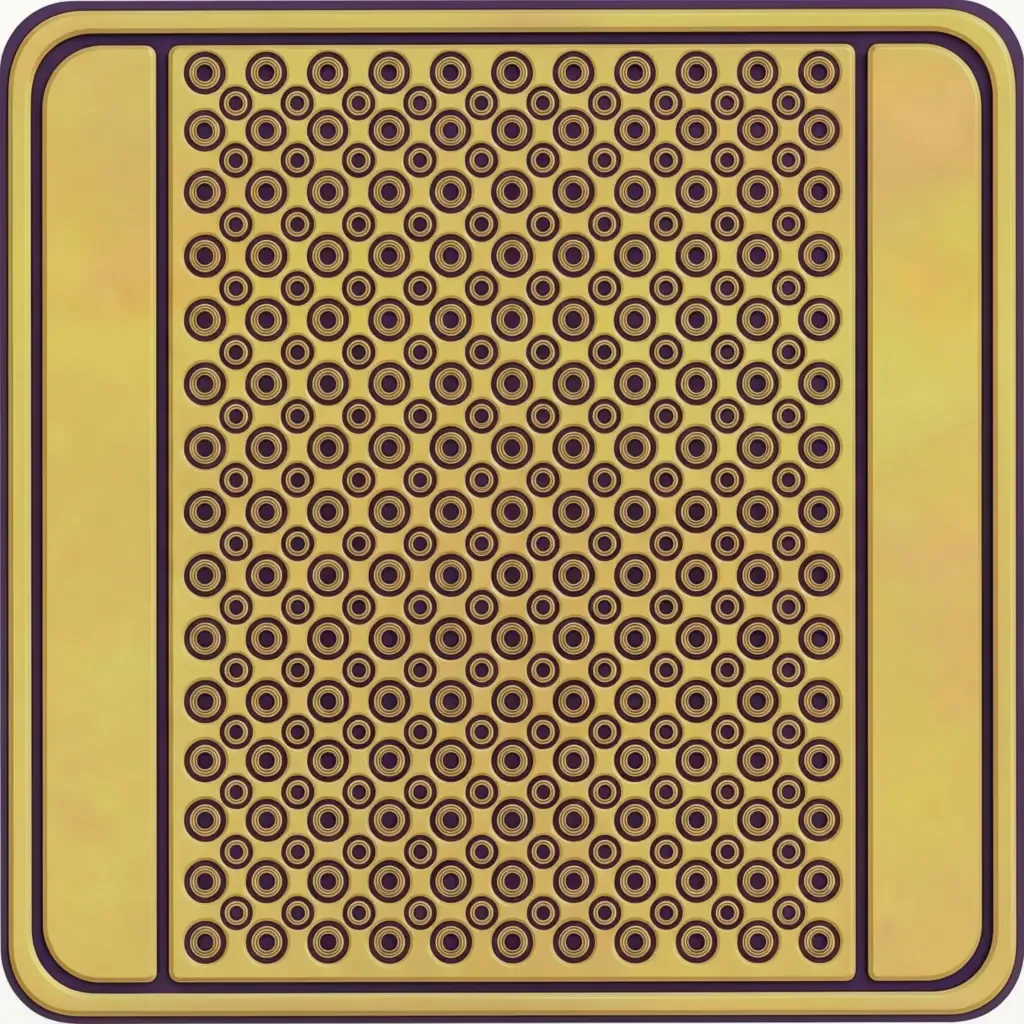
Square 100mW VCSEL Die
The square version uses a 300 × 300μm-class die and a 21-emitter configuration.
It provides 100mW minimum and 120mW typical optical output at 140mA under a 0.5ms pulse width and 1% duty cycle.
The square mechanical format can support package designs requiring a symmetrical die footprint and compact two-dimensional optical-source layout.
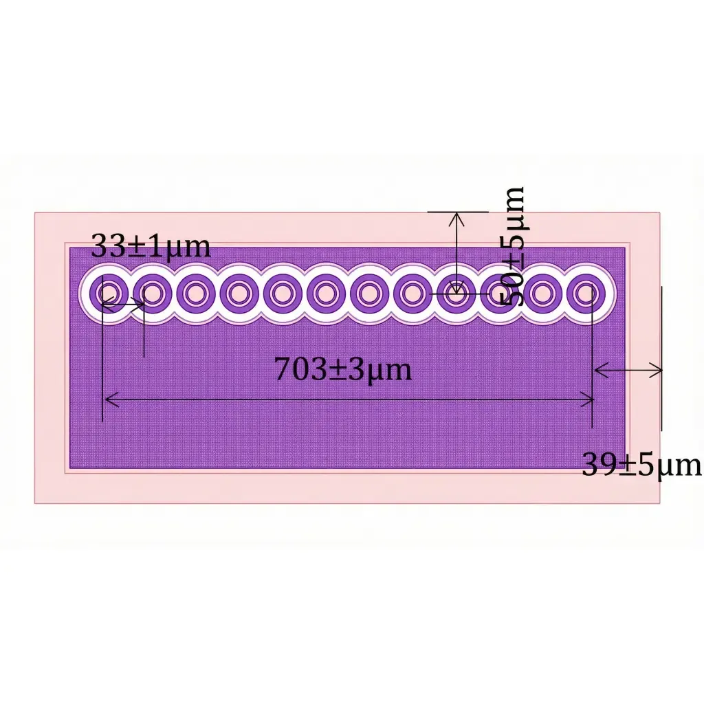
Rectangular 100mW VCSEL Die
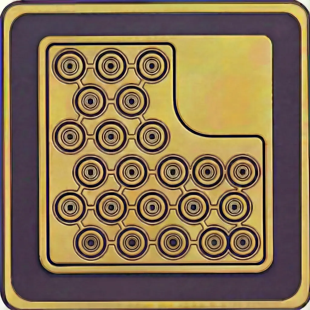
The rectangular version uses a 785 × 200μm-class die and a linear rectangular 22-emitter configuration.
It provides 110mW minimum, 120mW typical and 130mW maximum optical output at 140mA under a 0.1ms pulse width and 10% duty cycle.
The elongated die geometry can support package and optical-system designs requiring a rectangular source arrangement or a narrow mechanical layout.
Optical and Electrical Characteristics
The principal optical and electrical characteristics of the three versions are shown below.
Parameter | Compact Die | Square Die | Rectangular Die |
|---|---|---|---|
Peak Wavelength | 850nm typ. | 850nm typ. | 850nm typ. |
Wavelength Range | 840–860nm | 840–860nm | 840–860nm |
Threshold Current | 26mA typ. / 35mA max. | 25mA typ. / 35mA max. | 20mA min. / 25mA typ. / 30mA max. |
Forward Voltage | 1.9 / 2.05 / 2.2V | 1.9 / 2.1 / 2.3V | 1.9 / 2.1 / 2.2V |
Differential Resistance | 4Ω typ. | 5Ω typ. | 3Ω typ. |
Slope Efficiency | 0.9W/A min. / 1.0W/A typ. | 0.9W/A min. / 1.0W/A typ. | 0.9 / 1.05 / 1.2W/A |
Power Conversion Efficiency | 38% min. / 40% typ. | 38% min. / 40% typ. | 40 / 43 / 46% |
Beam Divergence, 1/e² | 18 / 20 / 23° | 17 / 20 / 23° | 19 / 20 / 23° |
The values above are model-specific and should be interpreted together with the corresponding pulse condition. The rectangular configuration remains in the established 100mW-class page grouping, while its source table specifies 110mW minimum, 120mW typical and 130mW maximum under the stated QCW condition.
A power value obtained using one pulse width or duty cycle should not be directly compared with another version without considering the complete electrical test condition.
All three versions are specified for QCW or pulse operation and should not be interpreted as continuous-wave devices.
3. Packaging, Optical Module and Application Development
The available die structures allow customers to select a mechanical format according to the package and optical-system architecture.
Mechanical Parameter | Compact Die | Square Die | Rectangular Die |
|---|---|---|---|
Die Size | 245 × 239μm | 300 × 300μm | 785 × 200μm |
Die Thickness | 100μm | 130μm | 130μm |
Number of Emitters | 23 | 21 | 22 |
Emitting Aperture | 10 ±1μm | Model-specific | 10 ±1μm |
Anode Pad | 96 × 100μm | 105μm-class | 752 × 108μm |
Backside Cathode | Full die area | Full die area | Full die area |
Possible integration directions include:
- Ceramic-submount assembly
- Custom SMD packaging
- TO-can package development
- Chip-on-board optical assemblies
- Multi-emitter optical-source modules
- Lens-integrated NIR sources
- Diffuser-integrated illumination modules
- Application-specific sensor packages
The selected version should be confirmed according to package space, bond-pad orientation, wire-bonding access, die-attach area, pulse-current path and external optical design.
The devices are ESD-sensitive and require suitable electrostatic protection during storage, handling, die placement, wire bonding, testing and package assembly.
Downstream Application Development
The 850nm 100mW VCSEL Bare Die options can support:
- Near-infrared sensing
- Proximity and presence detection
- Machine-vision source development
- Industrial optical detection
- Consumer-electronics optical sources
- Compact active illumination
- Optical alignment and beam evaluation
- Custom packaged VCSEL products
- Engineering and research systems
Die-Format Selection
The compact version is suitable where the smallest package footprint is important.
The square version supports mechanically symmetrical package and optical-source layouts.
The rectangular version supports elongated source geometries and package designs with narrow height or linear optical-layout requirements.
The final selection should consider both mechanical dimensions and electrical pulse conditions.
Sensing and Machine Vision
For sensing and machine-vision projects, product selection should consider working distance, receiver sensitivity, detector response, optical path, pulse synchronization, beam divergence and external lens structure.
Related Articles
4. Evaluation Kit and Documentation Support
The 850nm 100mW VCSEL Bare Die can be evaluated for die-format comparison, packaging trials, wire-bonding verification, driver evaluation and optical integration.
The Evaluation Kit includes: An Evaluation Kit with 10 pcs / KIT is available for project-specific verification, driver testing, thermal review, optical alignment and initial module integration.
- One selected 100mW VCSEL bare-die format per kit
- Corresponding product datasheet
- Die-dimension and assembly documentation
- International shipping quoted according to destination
Available evaluation options include:
- Compact die
- Square die
- Rectangular die
For component-level project evaluation, an Initial Product Report covering the Laser Diode Series and VCSEL Laser Diode Chip Series has been filed with the U.S. FDA CDRH. This filing supports technical documentation and product evaluation.
For applicable products, CE, EMC, EN 60825, LVD, RoHS, REACH and halogen-free certification and compliance documents are available. Documentation depends on the corresponding product model and does not represent certification of the customer's finished device.
5. Frequently Asked Questions
FAQ 1. What 850nm 100mW VCSEL bare-die formats are available?
Three formats are available: a compact 245 × 239μm die, a square 300 × 300μm die and a rectangular 785 × 200μm die.
The three versions use different emitter counts, pad layouts and pulse conditions.
They should be selected according to package space, optical-source geometry, wire-bonding access and driving requirements.
FAQ 2. Do all three 100mW VCSEL dies use the same test condition?
No.
The compact version is specified at 140mA with a 1ms pulse width and 10% duty cycle.
The square version is specified at 140mA with a 0.5ms pulse width and 1% duty cycle.
The rectangular version is specified at 140mA with a 0.1ms pulse width and 10% duty cycle.
The output values should always be interpreted together with the corresponding pulse condition.
FAQ 3. How should I select the correct 100mW die format?
Selection should consider available package dimensions, desired source geometry, bond-pad orientation, emitter arrangement, pulse width, duty cycle and optical-system design.
The compact die supports smaller package footprints, the square die supports symmetrical package layouts and the rectangular die supports elongated source geometries.
Final selection should be confirmed using the corresponding datasheet and the customer's package architecture.